
01
Precision
Multiband infrared centration measurement with self-calibration and center-of-curvature and vertex-image methods
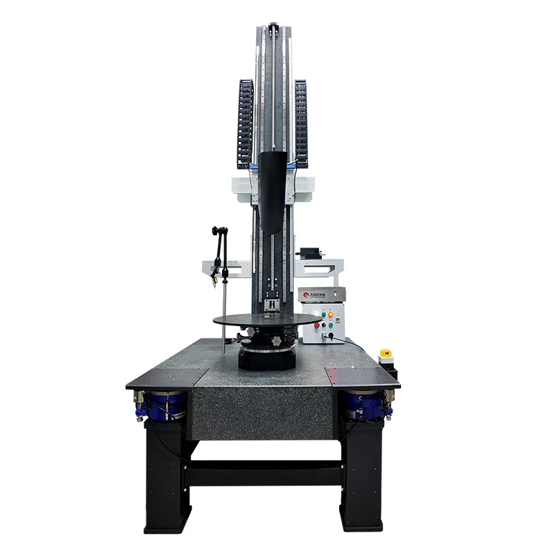
Infrared Centration
A multiband centration error measuring instrument for visible, MWIR, and LWIR optical assemblies, with ±2 μm decentering accuracy, self-calibration, and multiple measurement methods.
01
Multiband infrared centration measurement with self-calibration and center-of-curvature and vertex-image methods
02
Visible, MWIR, and LWIR optical system centration error and tilt
03
Multiband centration measurement systems covering visible, mid-wave infrared, and long-wave infrared optical systems.
ProductsInfrared Centration
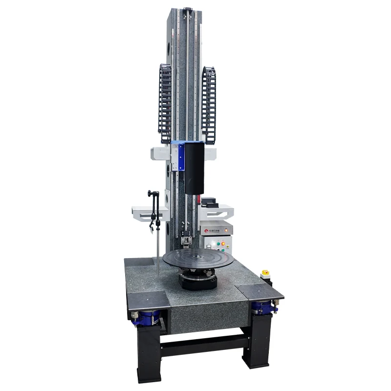
OCMAIR300 Multiband Infrared Centration Error Measuring Instrument
OCMAIR300 is designed for automated measurement of optical centration errors and precision centering alignment of visible-light lenses, infrared lenses, and optical assemblies. It covers the complete process of optical system centration measurement, optical alignment, and lens cementing for visible, mid-wave infrared (MWIR), and long-wave infrared (LWIR) systems.
OCMAIR300 achieves measurement accuracy of ≤ ±2 μm for decentering and ≤ ±5 arcsec for tilt. The instrument features proprietary engineering software for centration measurement and supports two methods based on the center-of-curvature image and the vertex image. Its integrated self-calibration function supports reliable measurement performance and convenient operation.
| Measurement Mode | Reflection mode using the center-of-curvature image and the vertex image |
|---|---|
| Infrared Operating Bands | Mid-wave infrared (MWIR): 3–5 μm; long-wave infrared (LWIR): 8–12 μm |
| Visible Operating Band | Visible light: 0.38–0.78 μm |
| Effective Guide Travel | 1,100 mm (customizable) |
| Turntable Diameter | Φ350 mm (customizable) |
| Air-Bearing Rotary Table Diameter | Φ300 mm (customizable) |
| Load Capacity | 100 kg |
| Overall Dimensions (L × W × H) | 1.5 × 1.5 × 2.5 m |
| Machine Weight | 2 t |
| Radius of Curvature Range of Measured Surfaces | −2,000 mm to +2,000 mm, including plane surfaces |
|---|---|
| Linear Decentering | ≤ 2 μm |
| Angular Decentering | ≤ 5 arcsec |
| Maximum Unobstructed Rotation Radius | 350 mm (700 mm diameter) |
| Model | Load Capacity (kg) | Diameter (mm) | Sample Height (mm) |
|---|---|---|---|
| OCMAIR600 | 1,000 | 800 | 1,800 |
| OCMAIR400 | 450 | 600 | 1,450 |
| OCMAIR300 | 125 | 400 | 1,100 |
| Centration Accuracy (Linear Decentering) | VIS: ±0.2 μm; IR: ±2 μm |
|---|---|
| Centration Accuracy (Angular Decentering) | VIS: ±2 arcsec; IR: ±5 arcsec |
| Measurable Radius of Curvature | ±2 mm to ±2,000 mm, including plane surfaces |
| Light Source Wavelength Range (Subject to Actual Delivery Configuration) | Mid-wave infrared: 4.5 ± 0.5 μm Long-wave infrared: 9.5 ± 0.5 μm Visible light: 633 ± 1 nm Laser light source |
| Detector | Standard visible-light detector: 2,048 × 1,536 (3.45 × 3.45 μm) Mid-/far-infrared detector: 640 × 512 (17 × 17 μm) |
| Objective Lens | 45 mm (optional), 90 mm (optional), 100 mm, 200 mm |
| Operating Temperature and Humidity Requirements | 22 ± 1°C; 30%–60% relative humidity |
| Operating Environment Requirements | VCC or higher |
| Air Supply Pressure Requirements | 0.6 MPa |
| Function | Provides tilt and translation adjustment capabilities |
|---|---|
| Translation Travel in Two Orthogonal Directions | ±5 mm |
| Tilt Adjustment Range in Two Orthogonal Directions | ±1.5° |
| Function | Non-contact measurement of annular zones |
|---|---|
| Z-Axis | Travel: 400 mm; control: motorized |
| X-Axis | Travel: 400 mm; control: manual |
| Probe Measurement Range | 3 mm |
| Probe Measurement Range Starting Point | 25 mm |
| Dynamic Resolution | 125 nm |
Product request
Share your sample type, dimensions, measurement target, accuracy requirement, and production environment. Our team will help match the system configuration to your application.
Explore more
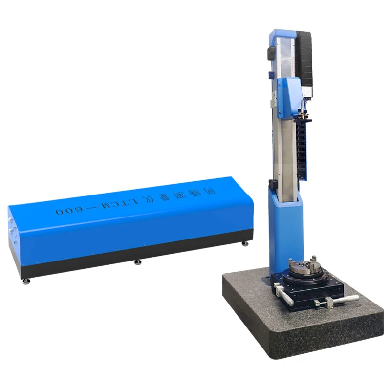
LTCM600
A non-contact short-coherence interferometry instrument for optical center thickness and air-gap measurement, with ±1 μm accuracy and ±0.5 μm repeatability.
View product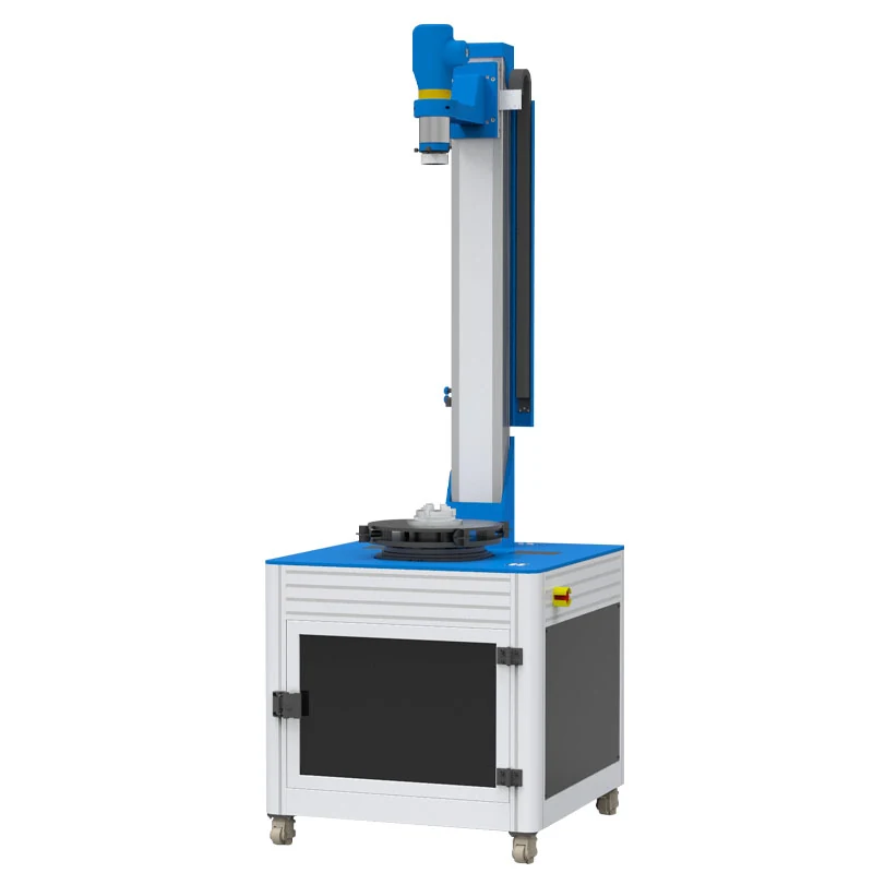
OCMAD-400
An upgraded dual-optical-path instrument for automated centration error measurement and centering alignment, with ±0.2 μm accuracy and software-guided assembly.
View product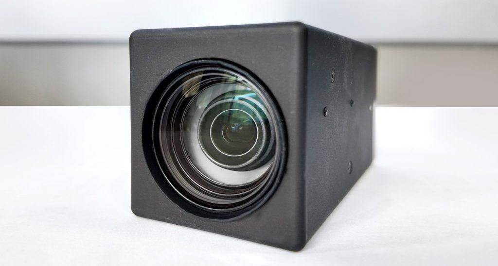
SZ01-F530-230SC
A compact, shock-resistant visible-light integrated camera system with 30x optical zoom, a 2 MP global-shutter CMOS sensor, HDR imaging, and HD-SDI output.
View product